MenuBar

Kata Mutiara

"Keberhasilan merupakan tetesan dari jeri-payah perjuangan, luka, pengorbanan dan hal-hal yang mengejutkan. Kegagalan merupakan tetesan dari kemalasan, kebekuan, kelemahan, kehinaan dan kerendahan"

ANIMASI TULISAN BERJALAN

Sunday, April 20, 2014

Ebook Gratis

Hai Sahabat blogger!!!
kali ini Saya memberikan informasi tentang Ebook Gratis yang bisa didownload oleh sahabat semuanya.
Siapapun yang lagi membutuhkan ebook-ebook dibawah ini ,Silahkan klik aja judul ebook nya!!!

1.  Eletromagnetic William Hayt Book sixth edition[2001]
2.  Renewable Energy
3. Ogata Control System Engineering 3th Edition
4.Ogata Control System Engineering 4th Edition
5. Ogata Control System Engineering 5th Edition
6.Teknologi Rekayasa Surya
7.Pengolahan Sinyal Digital dengan Pemrograman MATLab
8.Fisika untuk Sains dan Teknik jilid 2 [serway jeweet]
9.Mekanika Fluida
10.Termodinamika Teknik
11.Mekanika Klasik
12.Dinamika dan Mekanika untuk Perguruan Tinggi
13.Mekanika Fluida 1
14.Dasar-Dasar Getaran Mekanis
15.Panas dan Termodinamika
16.Essential MATLab [Brian D.Hahn]
17.Elementary Mathematical and Computa [C.G.Gibson]
18.Fundamental of Instrumentation [Dominique Placko]
19.Instrumentation and Application [John G. Webster]
20.Electronic Device and Circuit Theory seventh Edition [Robert L.Boylestad]
21.Finite element methods for electromagnetic [Stanley Humphries Jr.]
22.Digital Circuit Analysis and Design with an Introduction to CPLDs and FPGAs [Steven T.Karris]
23.Circuit Analysis with MATLab [Steven T.Karris]
24.  Textbook of Electrical Technology vol.1
25. Textbook of Electrical Technology vol.2
26. Amphibionic Build your own Reptilian Robot [Karl William]
27. Basic Circuit Analysis 2th edition 
28.C Programing for Microcontroller AVR , Joe Pardue & Smiley micros
29.C++ from the Ground up third edition Herbert Schildt
30.Calculus Varberg Purcell Rigdon 9 edition
31. Discrete Time Control System Katshuhik Ogata 
32. Electric Machinery Fundamental Chapman
33. Electromagnetism for Electronic Engineering
34. Electronic Circuit Analysis 2nd Editin Dr.K.Lal.Kishore 
36. Essential Electrodynamic 5th Edition Raymond Protheroe
37.  Essential Electrodynamic 5th Edition solution Raymond Protheroe 
38 General Chemistry 5th Edition James E.Brady
39.Mathematical Method for Physics a Concise Introduction
40. Practical Amplifier Diagram Jack Robin and Chaster
41. Process Industrial Instrument and Control Hand
42. Schaum Outline’s Programming with C 2nd Edition Byron Gottfried
43. Schaum Outline’s Mechanical Vibration 
44Theory and Problem of Trigonometry 3rd Edition Robert E.Moyer and Frank Ayres
45. Simple Program Design
46. Phisics With Answer
47. Numerical Method for Engieering Chapra Canale
48. C++ Programming Language
50. Pemograman C dan Implementasinya
51.The PIC Microcontroller Your Personal Introductory Course Third Edition
52.PICMicro Microcontroller Pocket References
53. Fundamental Of C Programming
54. Barnett Embedded C Programming and the ATMEL AVR
55. Thomas Calculus 11th edition
56. Solution Manual Thomas Calculus 11th edition 
57. M.R.Spiegel Vector Analysis Schaum series
58. Advanced Calculus and Analysis 
59. Advanced Engineering Mathematics 10th edition
60. 1000 solved Problem in Classical Physics 
61. Young and Freedman Solution Manual University of Physiscs 12 th Edition 
62. Classical Mechanics Golstein 
63. Solution Manual Classical Mechanics Golstein 
64. Fundamental of Physics 8 th

Saturday, April 12, 2014

Rankine cycle

The Rankine cycle is a model that is used to predict the performance ofsteam engines. The Rankine cycle is an idealised thermodynamic cycle of aheat engine that converts heat into mechanical work. The heat is supplied externally to a closed loop, which usually uses water as the working fluid. The Rankine cycle, in the form of steam engines, generates about 90% of all electric power used throughout the world,including virtually all biomasscoal,solar thermal and nuclear power plants. It is named after William John Macquorn Rankine, a Scottish polymath and Glasgow University professor.

Description

The Rankine cycle closely describes the process by which steam-operated heat engines commonly
 found in thermal power generation plants generate power. The heat sources used in these power plants are usually nuclear fission or the combustion of fossil fuels such as coalnatural gas, and oil.
The efficiency of the Rankine cycle is limited by the high heat of vaporization of the working fluid. Also, unless the pressure and temperature reach super critical levels in the steam boiler, the temperature range the cycle can operate over is quite small: steam turbine entry temperatures are typically 565°C (the creep limit of stainless steel) and steam condenser temperatures are around 30°C. This gives a theoretical maximum Carnot efficiency for the steam turbine alone of about 63% compared with an actual overall thermal efficiency of up to 42% for a modern coal-fired power station. This low steam turbine entry temperature (compared to a gas turbine) is why the Rankine (steam) cycle is often used as a bottoming cycle to recover otherwise rejected heat in combined-cycle gas turbine power stations.
The working fluid in a Rankine cycle follows a closed loop and is reused constantly. The water vapor with condensed droplets often seen billowing from power stations is created by the cooling systems (not directly from the closed-loop Rankine power cycle) and represents the means for (low temperature) waste heat to exit the system, allowing for the addition of (higher temperature) heat that can then be converted to useful work (power). This 'exhaust' heat is represented by the "Qout" flowing out of the lower side of the cycle shown in the T/s diagram below. Cooling towers operate as large heat exchangers by absorbing the latent heat of vaporization of the working fluid and simultaneously evaporating cooling water to the atmosphere. While many substances could be used as the working fluid in the Rankine cycle, water is usually the fluid of choice due to its favorable properties, such as its non-toxic and unreactive chemistry, abundance, and low cost, as well as its thermodynamic properties. By condensing the working steam vapor to a liquid the pressure at the turbine outlet is lowered and the energy required by the feed pump consumes only 1% to 3% of the turbine output power and these factors contribute to a higher efficiency for the cycle. The benefit of this is offset by the low temperatures of steam admitted to the turbine(s). Gas turbines, for instance, have turbine entry temperatures approaching 1500°C. However, the thermal efficiencies of actual large steam power stations and large modern gas turbine stations are similar.

The four processes in the Rankine cycle


There are four processes in the Rankine cycle. These states are identified by numbers (in brown) in the above Ts diagram.
  • Process 1-2: The working fluid is pumped from low to high pressure. As the fluid is a liquid at this stage the pump requires little input energy.
  • Process 2-3: The high pressure liquid enters a boiler where it is heated at constant pressure by an external heat source to become a dry saturated vapour. The input energy required can be easily calculated using mollier diagram or h-s chartor enthalpy-entropy chart also known as steam tables.
  • Process 3-4: The dry saturated vapor expands through a turbine, generating power. This decreases the temperature and pressure of the vapour, and some condensation may occur. The output in this process can be easily calculated using the Enthalpy-entropy chart or the steam tables.
  • Process 4-1: The wet vapour then enters a condenser where it is condensed at a constant pressure to become asaturated liquid.
In an ideal Rankine cycle the pump and turbine would be isentropic, i.e., the pump and turbine would generate no entropy and hence maximize the net work output. Processes 1-2 and 3-4 would be represented by vertical lines on the T-S diagramand more closely resemble that of the Carnot cycle. The Rankine cycle shown here prevents the vapor ending up in the superheat region after the expansion in the turbine,  which reduces the energy removed by the condensers.

Variables
\dot{Q}Heat flow rate to or from the system (energy per unit time)
\dot{m}Mass flow rate (mass per unit time)
\dot{W}Mechanical power consumed by or provided to the system (energy per unit time)
\eta_{therm}Thermodynamic efficiency of the process (net power output per heat input, dimensionless)
\eta_{pump},\eta_{turb}Isentropic efficiency of the compression (feed pump) and expansion (turbine) processes, dimensionless
h_1, h_2, h_3, h_4The "specific enthalpies" at indicated points on the T-S diagram
h_{4s}The final "specific enthalpy" of the fluid if the turbine were isentropic
p_1, p_2The pressures before and after the compression process
Equation
In general, the efficiency of a simple Rankine cycle can be defined as:
 \eta_{therm}=\frac{\dot{W}_{turbine}-\dot{W}_{pump}}{\dot{Q}_{in}} \approx \frac{\dot{W}_{turbine}}{\dot{Q}_{in}}.
Each of the next four equations[1] is easily derived from the energy and mass balance for a control volume. \eta_{therm} defines the thermodynamic efficiency of the cycle as the ratio of net power output to heat input. As the work required by the pump is often around 1% of the turbine work output, it can be simplified.
\frac{\dot{Q}_{in}}{\dot{m}}=h_3-h_2
\frac{\dot{Q}_{out}}{\dot{m}}=h_4-h_1
\frac{\dot{W}_{pump}}{\dot{m}}=h_2-h_1
\frac{\dot{W}_{turbine}}{\dot{m}}=h_3-h_4
When dealing with the efficiencies of the turbines and pumps, an adjustment to the work terms must be made.
 \frac{\dot{W}_{pump}}{\dot{m}} = h_2 - h_1 \approx \frac{v_1 \Delta p}{\eta_{pump}} = \frac{v_1 ( p_2 - p_1 )}{\eta_{pump}}
 \frac{\dot{W}_{turbine}}{\dot{m}} = h_3-h_4 \approx (h_3-h_4) \eta_{turbine}

Real Rankine cycle
In a real power plant cycle (the name 'Rankine' cycle is used only for the ideal cycle), the compression 
by the pump and the expansion in the turbine are not isentropic. In other words, these processes are non-reversible and entropy is increased during the two processes. This somewhat increases the powerrequired by the pump and decreases the power generated by the turbine.
In particular the efficiency of the steam turbine will be limited by water droplet formation. As the water condenses, water droplets hit the turbine blades at high speed causing pitting and erosion, gradually decreasing the life of turbine blades and efficiency of the turbine. The easiest way to overcome this problem is by superheating the steam. On the Ts diagram above, state 3 is above a two phase region of steam and water so after expansion the steam will be very wet. By superheating, state 3 will move to the right of the diagram and hence produce a drier steam after expansion.

Variation of the basic Rankine Cylce
The overall thermodynamic efficiency (of almost any cycle) can be increased by raising the average heat input temperature  \left( \bar{T}_\mathit{in} = \frac{\int_2^3 T\,ds}{Q_\mathit{in}} \right) 
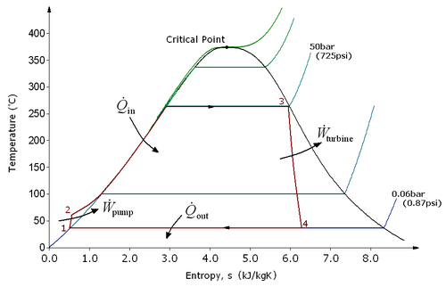
of that cycle. Increasing the temperature of the steam into the superheat region is a simple way of doing this. There are also variations of the basic Rankine cycle which are designed to raise the thermal efficiency of the cycle in this way; two of these are described below.

Rankine cycle with reheat[edit]


Rankine cycle with reheat
The purpose of a reheating cycle is to remove the moisture carried by the steam at the final stages of the expansion process. In this variation, twoturbines work in series. The first accepts vapor from the boiler at high pressure. After the vapor has passed through the first turbine, it re-enters the boiler and is reheated before passing through a second, lower-pressure, turbine. The reheat temperatures are very close or equal to the inlet temperatures, whereas the optimum reheat pressure needed is only one fourth of the original boiler pressure. Among other advantages, this prevents the vapor from condensingduring its expansion and thereby damaging the turbine blades, and improves the efficiency of the cycle, given that more of the heat flow into the cycle occurs at higher temperature. The reheat cycle was first introduced in the 1920s, but was not operational for long due to technical difficulties. In the 1940s, it was reintroduced with the increasing manufacture of high-pressure boilers, and eventually double reheating was introduced in the 1950s. The idea behind double reheating is to increase the average temperature. It was observed that more than two stages of reheating are unnecessary, since the next stage increases the cycle efficiency only half as much as the preceding stage. Today, double reheating is commonly used in power plants that operate under supercritical pressure.

Regenerative Rankine cycle[edit]


Regenerative Rankine cycle
The regenerative Rankine cycle is so named because after emerging from the condenser (possibly as a subcooled liquid) the working fluid is heated by steamtapped from the hot portion of the cycle. On the diagram shown, the fluid at 2 is mixed with the fluid at 4 (both at the same pressure) to end up with the saturated liquid at 7. This is called "direct contact heating". The Regenerative Rankine cycle (with minor variants) is commonly used in real power stations.
Another variation is where bleed steam from between turbine stages is sent tofeedwater heaters to preheat the water on its way from the condenser to the boiler. These heaters do not mix the input steam and condensate, function as an ordinary tubular heat exchanger, and are named "closed feedwater heaters".
The regenerative features here effectively raise the nominal cycle heat input temperature, by reducing the addition of heat from the boiler/fuel source at the relatively low feedwater temperatures that would exist without regenerative feedwater heating. This improves the efficiency of the cycle, as more of the heat flow into the cycle occurs at higher temperature. This process ensures cycle economy.

Organic Rankine cycle

The organic Rankine cycle (ORC) uses an organic fluid such as n-pentane or toluene in place of water and steam. This allows use of lower-temperature heat sources, such as solar ponds, which typically operate at around 70–90 °C The efficiency of the cycle is much lower as a result of the lower temperature range, but this can be worthwhile because of the lower cost involved in gathering heat at this lower temperature. Alternatively, fluids can be used that have boiling points above water, and this may have thermodynamic benefits. See, for example, mercury vapour turbine.


The Rankine cycle does not restrict the working fluid in its definition, so the name “organic cycle” is simply a marketing concept and the cycle should not be regarded as a separate thermodynamic cycle.

Supercritical Rankine cycle

The Rankine cycle applied using a supercritical fluid combines the concepts of heat regeneration and supercritical Rankine cycle into a unified process called the Regenerative Supercritical Cycle (RGSC) cycle. It is optimised for temperature sources 125 - 450°C.


pembuatan turbin uap


  • Turbin uap terdiri dari berbagai komponen penting contohnya bilah bergerak pada poros rotor, nosel (bilah diam) yang terpasang pada diafragma, perapat labirin, casing, bantalan, katup berhenti dan darurat, serta sistem pelumas.
  • Turbin uap dikelompokkan secara umum berdasarkan teknologi sebagai turbin uap "Impuls" dan "Reaksi" serta dalam penggunaannya sebagai turbin "Kondensasi" dan "Tekanan belakang" .
Video

BAGAIMANA CARA KERJA TURBIN


  • Uap ini mengalir melalui jalur uap yang dirancang secara optimal di dalam casing turbin uap. Jalur uap terdiri dari berbagai set bilah diam yang terpasang di diafragma casing dan satu set bilah bergerak yang terpasang di rotor di bagian keliling di atas disk. Setiap set bilah diam dan bergerak membentu satu tahap. Tahap tersebut yang banyak akan membentuk jalur uap. Bagian-bagian jalur uap dikategorikan sebagai tahap Tekanan Tinggi atau High pressure (HP), tahap Sedang atau Intermediate (IP) dan tahap Tekanan rendah atau Low Pressure (LP).
  • Profil bilah dan nosel (bilah diam) dirancang untuk memperkecil kerugian dan memaksimalkan ekstraksi pekerjaan dari aliran uap. Turbin uap dikelompokkan secara umum berdasarkan teknologi sebagai "Impuls" dan "Reaksi".
  • Uap akan mengembang saat mengalir dari tahap HP ke LP. Sebagai g antinya, tekanan dan suhu uap akan menurun, dan mengubah energi Panas (entalpi) di dalam uap menjadi energi kinetik, dan menyalur ke bilah bergerak sehingga akan memutar rotor.
  • Aliran uap masuk dikontrol melalui sistem kontrol yang terdiri dari mekanisme pengatur dan aktuator kecepatan dan sensor muatan yang mengontrol pergerakan kumparan pada katup aliran uap masuk, sehingga mengendalikan kecepatan di dalam kisaran performa turbin.
  • Dalam uap pembuangan turbin tekanan Belakang yang dibuang ke atmosfer atau digunakan untuk for proses / penukar panas. Di dalam turbin kondensasi, uap pembuangan akan dialirkan melalui kondensor di mana uap akan diubah menjadi air /air kondensasi dalam tekanan atmosfer, biasanya pada suhu 45°C. Air kondensasi ini dikumpulkan di dalam sumur panas dan akan dipakai lagi. Uap kondensasi dalam tekanan atmosfer akan meningkatkan penurunan entalpi di seluruh jalur uap dan memastikan konversi yang panas menjadi listrik yang efektif.
  • Ekstraksi terkontrol disediakan untuk turbin yang digunakan dalam penggunaan Pembangkitan bersama. Ekstraksi pada tingkat sedang mengisi uap ke proses dalam parameter uap yang diperlukan yang dialirkan melalui katup. Di sisi lain, ekstraksi yang tidak dikontrol dinamakan rembesan (bleed). Rembesan diperlukan untuk menyediakan uap bagi berbagai penggunaan pemanas contohnya Pemanas HP, Pemanas LP, uap penyegel, De-aerator juga persyaratan proses.
  • Turbin tekanan belakang digunakan di mana pabrik utama memerlukan uap proses berkelanjutan.
  • Turbin kondenassi ekstraksi biasanya digunakan untuk pencampuran panas dan listrik di mana syarat uap untuk proses atau Pertukaran Panas berbeda-beda tiap musimnya.
  • Jika dalam penggunaan penghasil listrik sederhana, suatu turbin kondensasi langsung digunakan untuk memaksimalkan ekstraksi pekerjaan dari energi panas aliran uap.

OXYGEN ANALYZER- ALAT UKUR EXCESS AIR


kandungan oksigen pada udara hasil pembakaran batubara, atau yang dikenal dengan istilah excess air. Udara hasil pembakaran batubara merupakan limbah dengan berbagai macam kandungan berbahaya seperti abu, SO2 dan NOx, disamping kandungan-kandungan lain seperti CO2 dan H2O. Selain itu juga ada O2 yang terkandung di dalamflue gas yang tidak ikut dalam proses pembakaran.
Oksigen ini jumlahnya dikontrol oleh sistem yang kompleks. Dengan tujuan untuk mendekati proses pembakaran batubara yang sempurna. Alat yang digunakan untuk “menghitung” kandungan oksigen dalam flue gas dinamakan Oxygen (O2) Analyzer. Alat ini sangat penting di dalam sebuah sistem PLTU karena sangat dekat hubungannya dengan efisiensi pembakaran batubara. Oleh karena itu di sebuah PLTU besar tidak hanya terpasang satu saja O2 analyzer, namun bisa sampai enam O2 analyzer. Untuk lebih memahami prinsip kerja dari O2 analyzer, mari kita amati gambar berikut.
20110727-113354.jpg
Udara proses (A) yang konsentrasi kandungan O2-nya tidak diketahui, mengalir di luar probe pengukur yang tertutup oleh sebuah elemen berbahan zirconium-oxide(B). Dan di sisi lain ada gas referensi (C) dengan kandungan oksigen yang diketahui mengalir di dalam elemen zirconium-oxide. Pada temperatur yang optimal, elemen ini diberikan tegangan listrik tertentu dalam mV. Dan pada temperatur yang konstan di elemen tersebut, besar tegangan ini hanya tergantung oleh perbandingan konsentrasi oksigen (partial pressure) antara (A) dan (C). Partial pressure adalah tekanan suatu gas apabila ia berada sendirian pada suatu volume tertentu. Pada suatu campuran gas yang ideal, masing-masing gas memiliki partial pressure sendiri-sendiri.
Menggunakan udara (dengan kandungan oksigen konstan 20,95%) sebagai gas referensi, tegangan yang diberikan pada elemen merupakan besaran langsung yang menunjukkan konsentrasi oksigen pada gas proses (A), hal ini menjelaskan adanya sifat isolasi antara gas proses dan gas referensi (pada elemen zirconium-oxide), yang besar perubahannya merupakan besar perubahan excess air dari flue gas.
Salah satu contoh panel oxygen analyzer
20110727-123724.jpg

PRINSIP KERJA TURBIN UAP


Turbin uap adalah suatu penggerak mula yang mengubah energi potensial menjadi energi kinetik dan energi kinetik ini selanjutnya diubah menjadi energi mekanik dalam bentuk putaran poros turbin. Poros turbin langsung atau dengan bantuan elemen lain, dihubungkan dengan mekanisme yang digerakkan. Tergantung dari jenis mekanisme yang digerakkan turbin uap dapat digunakan pada berbagai bidang industri, seperti untuk pembangkit listrik.


Komponen-komponen Turbin Uap

  Komponen-komponen utama pada turbin uap yaitu

Cassing yaitu sebagai penutup (rumah) bagian-bagian utama turbin.
 Rotor yaitu bagian turbin yang berputar terdiri dari:

1. Poros
Berfungsi sebagai komponen utama tempat dipasangnya cakram-cakram sepanjang sumbu.
2. Sudu turbin atau deretan sudu
Berfungsi sebagai alat yang menerima gaya dari energi kinetik uap melalui nosel.
3. Cakram
 Berfungsi sebagai tempat sudu-sudu dipasang secara radial pada poros.
4.   Nosel
Berfungsi sebagai media ekspansi uap yang merubah energi potensial menjadi energi kinetik.
5.   Bantalan (bearing)
Merupakan bagian yang berfungsi uuntuk menyokong kedua ujung poros dan banyak menerima beban.
6.   Perapat (seal)
Berfungsi untuk mencegah kebocoran uap, perapatan ini terpasang mengelilingi poros. Perapat yang digunakan adalah :
1. Labyrinth packing
2. Gland packing
7.    Kopling
Berfungsi sebagai penghubung antara mekanisme turbin uap dengan mekanisme yang digerakkan.

 Klasifikasi Turbin Uap

       Turbin Uap dapat diklasifikasikan menjadi beberapa kategori yang berbeda berdasarkan pada konstruksinya, prinsip kerjanya dan menurut peoses penurunan tekanan uap sebagai berikut :
1.      Klasifikasi Turbin berdasarkan Prinsip Kerjanya
a.       Turbin Impulse
Turbin impuls atau turbin tahapan impuls adalah turbin sederhana berrotor satu atau banyak (gabungan ) yang mempunyai sudu-sudu pada rotor itu. Sudu biasanya simetris dan mempunyai sudut masuk dan sudut keluar.
Ciri-ciri dari turbin impuls antara lain:

 Proses pengembangan uap / penurunan tekanan seluruhnya terjadi pada sudu diam / nosel.
Akibat tekanan dalam turbin sama sehingga disebut dengan Tekanan Rata.

b.      Turbin Reaksi
      Turbin reaksi mempunyai tiga tahap, yaitu masing-masingnya terdiri dari baris sudu tetap dan dua baris sudu gerak. Sudu bergerrak turbin reaksi dapat dibedakan dengan mudah dari sudu impuls karena tidak simetris, karena berfungsi sebagai nossel bentuknya sama dengan sudu tetap walaupun arahnya lengkungnya berlawanan.
Ciri-ciri turbin ini adalah :

Penurunan tekanan uap sebagian terjadi di Nosel dan Sudu  Gerak
Adanya perbedaan tekanan didalam turbin sehingga disebut Tekanan Bertingkat.


2.      Klasifikasi turbin uap berdasarkan pada tingkat penurunan Tekanan Dalam Turbin


Turbin Tunggal ( Single Stage )

          Dengan kecepatan satu tingkat atau lebih turbin ini cocok untuk untuk daya kecil, misalnya penggerak            kompresor, blower, dll.
     2.  Turbin Bertingkat  (Aksi dan Reaksi ).
           Disini sudu-sudu turbin dibuat bertingkat, biasanya cocok untuk daya besar. Pada turbin bertingkat                terdapat deretan sudu 2 atau lebih. Sehingga turbin tersebut terjadi distribusi kecepatan / tekanan.

3.      Klasifikasi turbin berdasarkan Proses Penurunan Tekanan Uap

    1.  Turbin Kondensasi.

         Tekanan keluar turbin kurang dari 1 atm dan dimasukkan kedalam kompresor.
    2.  Turbin Tekanan Lawan.

         Apabila tekanan sisi keluar turbin masih besar dari  1 atm     sehingga masih dapat dimanfaatkan untuk           menggerakkan turbin lain.
    3.  Turbin Ekstraksi.

          Didalam turbin ini sebagian uap dalam turbin diekstraksi untuk roses pemanasan lain,  misalnya proses           industri.

Prinsip kerja turbin uap


       Turbin uap terdiri dari sebuah cakram yang dikelilingi oleh daun-daun cakram yang disebut sudu-sudu. Sudu-sudu ini berputar karena tiupan dari uap bertekanan yang berasal dari ketel uap, yang telah dipanasi terdahulu dengan menggunakan bahan bakar padat, cair dan gas.
Uap tersebut kemudian dibagi dengan menggunakan control valve yang akan dipakai untuk memutar turbin yang dikopelkan langsung dengan pompa dan juga sama halnya dikopel dengan sebuah generator singkron untuk menghasilkan energi listrik.
Setelah melewati turbin uap, uap yang bertekanan dan bertemperatur tinggi tadi muncul menjadi uap bertekanan rendah. Panas yang sudah diserap oleh kondensor menyebabkan uap berubah menjadi air yang kemudian dipompakan kembali menuju boiler. Sisa panas dibuang oleh kondensor mencapai setengah jumlah panas semula yang masuk. Hal ini mengakibatkan efisisensi thermodhinamika  suatu turbin uap bernilai lebih kecil dari 50%. Turbin uap yang modern mempunyai temperatur boiler sekitar 5000C sampai 6000C dan temperatur kondensor 200C sampai 300C.

Turbin Uap


Sebuah sistem turbin uap – generator yang digunakan untuk pembangkit listrik tenaga uap berfungsi untuk mengkonversikan energi panas dari uap air menjadi energi listrik. Proses yang terjadi adalah energi panas yang ditunjukkan oleh gradien/perubahan temperatur dikonversikan oleh turbin menjadi energi kinetik dan sudu-sudu turbin mengkonversikan energi kinetik ini menjadi energi mekanik pada poros/shaft. Pada akhirnya, generator mengkonversikan energi mekanik menjadi energi listrik. Panas dari uap air yang tidak terkonversi menjadi energi mekanik, terdisipasi/dibuang di kondenser oleh air pendingin.
Turbin Uap Multistage
20110807-075921.jpg
Umumnya PLTU menggunakan turbin uap tipemultistage, yakni turbin uap yang terdiri atas lebih dari 1stage turbin (Turbin High Pressure, Intermediate Pressure, dan Low Pressure). Uap air superheater yang dihasilkan oleh boiler masuk ke turbin High Pressure(HP), dan keluar pada sisi exhaust menuju ke boiler lagi untuk proses reheater. Uap air yang dipanaskan kembali ini dimasukkan kembali ke turbin uap sisi Intermediate Pressure (IP), dan uap yang keluar dari turbin IP akan langsung masuk ke Turbin Low Pressure (LP). Selanjutnya uap air yang keluar dari turbin LP masuk ke dalam kondenser untuk mengalami proses kondensasi.
Berikut adalah beberapa bagian-bagian penting dari turbin uap:
1. Shaft Seals
Shaft seals adalah bagian dari turbin antara poros dengan casing yang berfungsi untuk mencegah uap air keluar dari dalam turbin melewati sela-sela antara poros dengan casing akibat perbedaan tekanan dan juga untuk mencegah udara masuk ke dalam turbin (terutama turbin LP karena tekanan uap air yang lebih vakum) selama turbin uap beroperasi.
Turbin uap menggunakan sistem labyrinth seal untukshaft seals. Sistem ini berupa bagian yang berkelak-kelok pada poros dan casing-nya yang kedua sisinya saling bertemu secara berselang-seling. Antaralabyrinth poros dengan labyrinth casing ada sedikit rongga dengan jaraj tertentu. Sistem ini bertujuan untuk mengurangi tekanan uap air di dalam turbin yang masuk ke sela-sela labyrinth sehingga tekanan antara uap air dengan udara luar akan mencapai nilai yang sama pada titik tertentu.
Prinsip dan Jenis Labyrinth Seals
20110807-092621.jpg
20110807-092632.jpg
Selain adanya sistem labyrinth seal, ada satu sistem tambahan bernama sistem seal & gland steam. Sistem ini bertugas untuk menjaga tekanan di labyrinth sealpada nilai tertentu terutama pada saat start up awal atau shut down turbin dimana pada saat tersebut tidak ada uap air yang masuk ke dalam turbin uap.
2. Turbine Bearings
Bearing / bantalan pada turbin uap memiliki fungsi sebagai berikut:
  • Menahan diam komponen rotor secara aksial
  • Menahan berat dari rotor
  • Menahan berbagai macam gaya tidak stabil dari uap air terhadap sudu turbin
  • Menahan gaya kinetik akibat dari sisa-sisa ketidakseimbangan atau ketidakseimbangan karena kerusakan sudu (antisipasi)
  • Menahan gaya aksial pada beban listrik yang bervariasi
Jenis bearing yang digunakan dalam desain turbin uap yaitu thrust bearing, journal bearing, dan kombinasi antara keduanya. Selain itu juga dibutuhkan sebuah sistem pelumasan menggunakan oli, yang secara terus-menerus disirkulasi dan didinginkan untuk melumasibearing yang terus mengalami pergesekan pada saat turbin uap beroperasi normal.
3. Balance Piston
Pada turbin uap, ada 50%ngaya reaksi dari sudu yang berputar menghasilkan gaya aksial terhadap sisi belakang dari silinder pertama turbin, gaya inilah yang perlu dilawan oleh sistem balance piston.
4. Turbine Stop Valves
Atau disebut juga Emergency Stop Valve karena berfungsi untuk mengisolasi turbin dari supply uap air pada keadaan darurat untuk menghindari kerusakan atau juga overspeed.
5. Turbine Control Valve
Berfungsi untuk mengontrol supply dari uap air yang masuk ke dalam turbin sesuai dengan sistem kontrol yang bergantung pada besar beban listrik.
6. Turning Device
Adalah suatu mekanisme untuk memutar rotor dari turbin pada saat start awal atau pada saat setelah shut down untuk mencegah terjadinya distorsi/bendingakibat dari proses pemanasan atau pendinginan yang tidak seragam pada rotor.

iklan

iklan